Wednesday 29 May 2013

HSRP -Hot Standby Router Protocol

Hot Standby Router Protocol (HSRP) is a Cisco proprietary redundancy protocol for establishing a fault-tolerant default gateway


Virtual Router Redundancy Protocol (VRRP)


The Virtual Router Redundancy Protocol (VRRP) is an election protocol that dynamically assigns
responsibility for one or more virtual routers to the VRRP routers on a LAN, allowing several routers on
a multiaccess link to utilize the same virtual IP address. A VRRP router is configured to run the VRRP
protocol in conjunction with one or more other routers attached to a LAN. In a VRRP configuration, one
router is elected as the virtual router master, with the other routers acting as backups in case the virtual
router master fails.


There are several ways a LAN client can determine which router should be the first hop to a particular
remote destination. The client can use a dynamic process or static configuration. Examples of dynamic
router discovery are as follows:
• Proxy ARP—The client uses Address Resolution Protocol (ARP) to get to the destination it wants
to reach, and a router will respond to the ARP request with its own MAC address.
• Routing protocol—The client listens to dynamic routing protocol updates (for example, from
Routing Information Protocol [RIP]) and forms its own routing table.
• ICMP Router Discovery Protocol (IRDP) client—The client runs an Internet Control Message
Protocol (ICMP) router discovery client.


VRRP is supported on Fast Ethernet, BVI, and Gigabit Ethernet interfaces, on MPLS VPNs, VRF-aware
MPLS VPNs, and VLANs.


VRRP Benefits

Redundancy
VRRP enables you to configure multiple routers as the default gateway router, which reduces the
possibility of a single point of failure in a network.
Load Sharing
You can configure VRRP in such a way that traffic to and from LAN clients can be shared by multiple
routers, thereby sharing the traffic load more equitably among available routers.
Multiple Virtual Routers
VRRP supports up to 255 virtual routers (VRRP groups) on a router physical interface, subject to the
platform supporting multiple MAC addresses. Multiple virtual router support enables you to implement
redundancy and load sharing in your LAN topology.
Multiple IP Addresses
The virtual router can manage multiple IP addresses, including secondary IP addresses. Therefore, if you
have multiple subnets configured on a GigabitEthernet interface, you can configure VRRP on each
subnet.

Preemption
The redundancy scheme of VRRP enables you to preempt a virtual router backup that has taken over for
a failing virtual router master with a higher priority virtual router backup that has become available.
Advertisement Protocol
VRRP uses a dedicated Internet Assigned Numbers Authority (IANA) standard multicast address
(224.0.0.18) for VRRP advertisements. This addressing scheme minimizes the number of routers that
must service the multicasts and allows test equipment to accurately identify VRRP packets on a segment.
The IANA assigned VRRP the IP protocol number 112.


SUMMARY STEPS
1. enable
2. configure terminal
3. interface type number
4. ip address ip-address mask
5. vrrp group description text
6. vrrp group priority level
7. vrrp group preempt [delay minimum seconds]
8. vrrp group timers advertise [msec] interval
9. vrrp group timers learn
10. exit
11. no vrrp sso


Bridge Group Virtual Interface - BVI


Cisco Bridge-group Virtual Interface (BVI)

BVI (Bridge Group Virtual Interface) is a routed interface that represents a set of Ethernet interfaces that gets bridged. By using  a Bridge group Virtual Interface, you can convert  multiple Router Ethernet WAN interfaces as members of a common Ethernet broadcast domain 
Fig. Bridging Ethernet Interfaces
This configuration allows bridging IP between two Ethernet interfaces, and routing IP from bridgedinterfaces using a Bridge Virtual Interface (BVI). By using Integrated Routing and Bridging (IRB)technique, a Cisco router  can be turned into a L3 switch. Ip addresses can be assigned on Bridge-Group Virtual Interfaces (BVIs), similar to VLAN interfaces as in L3 switches. A BVI is a virtual routed interface that has all network layer attributes, eg: a network address can be assigned to it and does not support bridging.
Bridge groups are defined by a unique number and are used for router bridging configuration. Network traffic is bridged between all interfaces that belong to the same bridge group.

Step by Step Bridge Group Virtual Interface (BVI) Configuration

Integrated Routing and Bridging configuration on Router1:
Router (config)#int fa0/0
Router (config-if)#bridge-group 1
Router (config-if)#no shut
Router(config-if)#exit
Router (config)#
Router (config-if)#int fa1/0
Router(config-if)#bridge-group 1
Router (config-if)#no shut
Router(config-if)#exit
Router(config)#

Create Bridge Group Virtual Interface (BVI) and configure the IP and Routing credentials.

Router1(config)#bridge irb
Router (config)#int bvi1
Router(config-if)#ip add 192.168.2.1 255.255.255.0
Router(config-if)#exit
Router(config)#bridge 1 protocol ieee
Router (config)#bridge 1 route ip
Router(config)#
Note: The bridge 1 protocol ieee global configuration command removes bridge-group 1 spanning-disabled interface subcommand on Fa0/0 and Fa1/0 and hence enables STP on bridged interfaces.

Find Bridge Group Virtual Interface (BVI) show command outputs

Router#sh spanning-tree brief
Bridge group 1
Spanning tree enabled protocol ieee
Root ID    Priority    32768
Address     cc01.01e0.0000
This bridge is the root
Hello Time   2 sec  Max Age 20 sec  Forward Delay 15 sec
Bridge ID  Priority    32768
Address     cc01.01e0.0000
Hello Time   2 sec  Max Age 20 sec  Forward Delay 15 sec
Aging Time 300

Interface                                   Designated
Name                 Port ID Prio Cost  Sts Cost  Bridge ID            Port ID
——————– ——- —- —– — —– ——————– —–
FastEthernet0/0      128.2    128    19 FWD     0 32768 cc01.01e0.0000 128.2
FastEthernet1/0      128.3    128    19 FWD     0 32768 cc01.01e0.0000 128.3

Router#sh bridge group
Bridge Group 1 is running the IEEE compatible Spanning Tree protocol
Port 2 (FastEthernet0/0) of bridge group 1 is forwarding
Port 3 (FastEthernet1/0) of bridge group 1 is forwarding

show interfaces [interface] irb
This command displays the protocols that can be routed or bridged for the specified interface, as follows:
Router#show interface e0 irb
Ethernet0
Routed protocols on Ethernet0:
ip
Bridged protocols on Ethernet0:
ip         ipx
IP protocol is routed as well as bridged.
Software MAC address filter on Ethernet0
Hash Len    Address      Matches  Act      Type
0×00:  0 ffff.ffff.ffff     0     RCV  Physical broadcast
0x2A:  0 0900.2b01.0001     0     RCV  DEC spanning tree
0x9E:  0 0000.0c3a.5092     0     RCV  Interface MAC address
0x9E:  1 0000.0c3a.5092     0     RCV  Bridge-group Virtual Interface
0xC0:  0 0100.0ccc.cccc    157    RCV  CDP
0xC2:  0 0180.c200.0000     0     RCV  IEEE spanning tree
0xC2:  1 0180.c200.0000     0     RCV  IBM spanning tree

Tuesday 28 May 2013

Internet Protocol address (IP Address )

Ip address belongs to OSI  3rd  layer (network layer)  and it a logical address to identify a device on TCP/IP network .
we have two options for IP address

1. IPV4 (IP version 4)
2. IPV6 (IP  version 6)

           
The format of an IPV4 address is a 32-bit numeric address written as four part separated by periods. Each parts are called Octet (8Bit number system). IPV4 is divided into 4 classes .


    0-255
  0-255
  0-255
0-255
First Octet
Second Octet
Third Octet
Fourth Octet


Based on the value of first octet we can understand the IP belongs to which class.


Class A
1.0.0.0 –  126.255.255.255
Class B
128.0.0.0- 191.255.255.255
Class C
192.0.0.0-223.255.255.255
Class D
224.0.0.0-239.255.255.255
Class E
240.0.0.0-255.255.255.255

  
An IP address can be static or dynamic. A static IP address will never change and it is a permanent Internet address. A dynamic IP address is a temporary address that is assigned from DHCP Server in the Network.

IANA-reserved private IPv4 network ranges


Class A
10.0.0-10.255.255.255
Class B
172.16.0.0.-172.31.255.255
Class C
192.168.0.0-192.168.255.255

Network identify by 1 and Host identified by 0.

Mask
Class A
255.0.0.0
Class B
255.255.0.0
Class C
255.255.255.0
Class D
 Multicasting
Class E
Experimental

The MASK is used to describe how may networks and how many host per network  in IPV4 classes.
ie. In Class A - MASK =255.0.0.0 =11111111.00000000.00000000.00000000
Network Bit= 11111111=8Bit
Host Bit =00000000.00000000.00000000 = 24Bit

In Class A  total 2^8 Network and 2^24 Hosts.
In  Class B Network=2^16 and Host=2^16
In Class C Network=2^24 and Host=2^8


Overview of Exchange 2010 Server Roles


A server role is a unit that logically groups the required features and components needed to perform a specific function in the messaging environment. The requirement of a server role is that it is a server that could be run as an atomic unit of scalability. A server role is composed of a group of features.
Server roles, the primary unit of deployment, enable administrators to easily choose which features are installed on an Exchange server. Logically grouping features in server roles offers the following advantages:
  • Reduces attack surface on an Exchange server.
  • Allows you to install and configure an Exchange server the way you intend to use it.
  • Offers the ability to fully customize a server to support your business goals and needs.
The following figure illustrates a domain with each server role deployed.
A domain with each server role deployed
Exchange 2010 includes the following server roles:
  • Mailbox Server   This server hosts mailboxes and public folders. For more information about the Exchange 2010 Mailbox server role
  • Client Access Server   This is the server that hosts the client protocols, such as Post Office Protocol 3 (POP3), Internet Message Access Protocol 4 (IMAP4), Secure Hypertext Transfer Protocol (HTTPS), Outlook Anywhere, Availability service, and Autodiscover service. The Client Access Server also hosts Web services. For more information about the Exchange 2010 Client Access server role
  • Unified Messaging Server   This is the server that connects a Private Branch eXchange (PBX) system to Exchange 2010. For more information about the Exchange 2010 Unified Messaging server role

  • Hub Transport Server   This is the mail routing server that routes mail within the Exchange organization. For more information about the Exchange 2010 Hub Transport server role
  • .
  • Edge Transport Server   This is the mail routing server that typically sits at the perimeter of the topology and routes mail in to and out of the Exchange organization. For more information about the Exchange 2010 Edge Transport server role

Overview of the Mailbox Server Role

In Microsoft Exchange Server 2010, the Mailbox server role is one of several server roles that you can install and configure on a server running Windows Server 2008. The Mailbox server role is the most common server role and is at the core of an Exchange organization. Servers on which the Mailbox server role is installed are called Mailbox servers.
Mailbox servers perform the following functions:
  • Host mailbox databases
  • Provide e-mail storage
  • Host public folder databases
  • Calculate e-mail address policies
  • Generate address lists and offline address books (OABs)
  • Conduct Multi-Mailbox Searches
  • Provide high availability and site resiliency
  • Provide content indexing
  • Provide messaging records management (MRM) and retention policies

Client Access

In Microsoft Exchange Server 2010, the Client Access server role supports the Outlook Web App and Microsoft Exchange ActiveSync client applications, and the Post Office Protocol version 3 (POP3) and Internet Message Access Protocol version 4rev1 (IMAP4) protocols. The Client Access server role also provides access to free/busy data by using the Availability service and enables certain clients to download automatic configuration settings from the Autodiscover service. You must install the Client Access server role in every Exchange organization and every Active Directory site that has the Mailbox server role installed.

Unified Messaging


Unified Messaging combines voice messaging and e-mail into one Inbox, which can be accessed from the telephone and the computer. Unified Messaging integrates Exchange Server 2010 with the telephony network in your organization and brings the features found in Unified Messaging to the core of the Exchange Server product line.

Overview of the Hub Transport Server Role


Deployed inside your Active Directory forest, the Hub Transport server role handles all mail flow inside the organization, applies transport rules, applies journaling policies, and delivers messages to a recipient's mailbox. Messages that are sent to the Internet are relayed by the Hub Transport server to the Edge Transport server role that's deployed in the perimeter network. Messages that are received from the Internet are processed by the Edge Transport server before they're relayed to the Hub Transport server. If you don't have an Edge Transport server, you can configure the Hub Transport server to relay Internet messages directly or utilize a third-party smart host. You can also install and configure the Edge Transport server agents on the Hub Transport server to provide anti-spam and antivirus protection inside the organization, although this isn't recommended.
You can install the Hub Transport server role on the same hardware with any other internal server role or on a server that's dedicated to the Hub Transport server role. You must deploy a Hub Transport server role in each Active Directory site that contains a Mailbox server role. Deploying more than one Hub Transport server per site provides redundancy. When you install more than one Hub Transport server in an Active Directory site, the connections are distributed.
The message-processing scenarios that you can manage on the Hub Transport server role are described in the following sections.

The Hub Transport server role processes all messages that are sent inside the Microsoft Exchange Server 2010 organization before the messages are delivered to a recipient's Inbox or are routed to users outside the organization. There are no exceptions to this behavior; messages are always passed through a server that runs the Hub Transport server role.
Messages are submitted to the Hub Transport server in three ways: through SMTP submission, from the Pickup directory, or when a user inside the organization sends a message, which is picked up from the user's Outbox by the store driver. The store driver is a software component of the Hub Transport server that delivers inbound messages to Exchange stores, the databases that contain public folder and mailbox stores.
When messages are submitted to the Hub Transport server, they're processed by the categorizer. The categorizer is a component of Exchange transport that processes all inbound messages and determines what to do with the messages based on information about the intended recipients. In Exchange 2010, the Hub Transport server uses the categorizer to expand distribution lists and to identify alternative recipients and forwarding addresses. After the categorizer retrieves full information about the recipients, it uses that information to apply policies, route the messages, and perform content conversion. Messages are then delivered locally by the store driver to a recipient's mailbox, or they're delivered remotely by using SMTP to send messages to another transport server. Messages that are sent by users in your organization are picked up from the sender's Outbox by the store driver and are put in the Submission queue on a server that runs the Hub Transport server role.
With a collection of transport agents, you can configure rules and settings that are applied as messages enter and leave the mail flow components. You can create messaging policy and rule settings that are designed to meet different regulations and that can easily be changed to adapt to your organization's requirements. The transport-based messaging policy and compliance features include server-based rules that you configure to enforce your organization's compliance scenarios and the Journaling agent that acts to enforce message retention. For more information
Exchange 2010 provides anti-spam and antivirus protection for messages. Although these features are designed for use in the perimeter network on the Edge Transport server role, the Edge Transport agents can also be configured on the Hub Transport server. By default, these agents aren't enabled on the Hub Transport server role. To use the anti-spam features on the Hub Transport server, you must register the agents in a configuration file and enable the features that you want to use by running a provided Exchange Management Shell script. You install and enable the antivirus agent in a separate operation. For more information

Overview of the Edge Transport Server Role


In Microsoft Exchange Server 2010, the Edge Transport server role is deployed in your organization's perimeter network. Designed to minimize the attack surface, the Edge Transport server handles all Internet-facing mail flow, which provides SMTP relay and smart host services for the Exchange organization. Additional layers of message protection and security are provided by a series of agents that run on the Edge Transport server and act on messages as they're processed by the message transport components. These agents support the features that provide protection against viruses and spam and apply transport rules to control message flow.
The computer that has the Edge Transport server role installed doesn't have access to Active Directory. All configuration and recipient information is stored in Active Directory Lightweight Directory Services (AD LDS). To perform recipient lookup tasks, the Edge Transport server requires data that resides in Active Directory. This data is synchronized to the Edge Transport server using EdgeSync. EdgeSync is a collection of processes that are run on a computer that has the Hub Transport server role installed to establish one-way replication of recipient and configuration information from Active Directory to the AD LDS instance on an Edge Transport server. The Microsoft Exchange EdgeSync service copies only the information that's required for the Edge Transport server to perform anti-spam configuration tasks and the information about the connector configuration that's required to enable end-to-end mail flow. The Microsoft Exchange EdgeSync service performs scheduled updates so that the information in AD LDS remains current.
You can install more than one Edge Transport server in the perimeter network. Deploying more than one Edge Transport server provides redundancy and failover capabilities for your inbound message flow. You can load-balance SMTP traffic to your organization between Edge Transport servers by defining more than one mail exchange (MX) resource record with the same priority in the Domain Name System (DNS) database for your mail domain. You can achieve consistency in configuration between multiple Edge Transport servers by using cloned configuration scripts.
The message-processing scenarios that you can manage on the Edge Transport server role are described in the following sections.

Servers that run the Edge Transport server role accept messages that come into the Exchange 2010 organization from the Internet. After the messages are processed by the Edge Transport server, they are routed to Hub Transport servers inside the organization.
All messages that are sent to the Internet from the organization are routed to Edge Transport servers after the messages are processed by the Hub Transport server. You can configure the Edge Transport server to use DNS to resolve MX resource records for external SMTP domains, or you can configure the Edge Transport server to forward messages to a smart host for DNS resolution.

In Exchange 2010, the anti-spam and antivirus features provide services to block viruses and spam, or unsolicited commercial e-mail, at the network perimeter. Most viruses use spam-like tactics to gain access to your organization and to entice users to open an e-mail message. If you can filter out most of your spam, you're also more likely to capture viruses before they enter your organization.
Spammers use a variety of techniques to send spam into your organization. Servers that run the Edge Transport server role help prevent users in your organization from receiving spam by providing a collection of agents that work together to provide different layers of spam filtering and protection. Establishing tarpitting intervals on connectors makes e-mail harvesting attempts ineffective.

Edge Transport rules are used to control the flow of messages that are sent to or received from the Internet. The Edge Transport rules help protect corporate network resources and data by applying an action to messages that meet specified conditions. These rules are configured for each server. Edge Transport rule conditions are based on data, such as specific words or text patterns in the message subject, body, header, or From address, the spam confidence level (SCL), or attachment type. Actions determine how the message is processed when a specified condition is true. Possible actions include quarantine of a message, dropping or rejecting a message, appending additional recipients, or logging an event. Optional exceptions exempt particular messages from having an action applied.

You use address rewriting to present a consistent appearance to external recipients of messages from your Exchange 2010 organization. You configure the Address Rewriting agent on the Edge Transport server role to enable the modification of the SMTP addresses on inbound and outbound messages. Address rewriting is especially useful when a newly merged organization that has several domains wants to present a consistent appearance of e-mail addresses to external recipients.

Friday 24 May 2013

Cisco Secure Access Control Server (ACS)


Cisco Secure Access Control Server (ACS) is an access policy control platform that helps you comply with growing regulatory and corporate requirements. By integrating with your other access control systems, it helps improve productivity and contain costs. It supports multiple scenarios simultaneously, including:
  • Device administration: Authenticates administrators, authorizes commands, and provides an audit trail
  • Remote Access: Works with VPN and other remote network access devices to enforce access policies
  • Wireless: Authenticates and authorizes wireless users and hosts and enforces wireless-specific policies
  • Network admission control: Communicates with posture and audit servers to enforce admission control policies


Cisco Secure ACS lets you centrally manage access to network resources for a growing variety of access types, devices, and user groups. These key features address the current complexities of network access control:
    • Support for a range of protocols including Extensible Authentication Protocol (EAP) and non-EAP protocols provides the flexibility to meet all your authentication requirements
    • Integration with Cisco products for device administration access control allows for centralized control and auditing of administrative actions
    • Support for external databases, posture brokers, and audit servers centralizes access policy control and lets you integrate identity and access control systems

Cisco Network Admission Control System (NAC)


With Cisco NAC Appliance (formerly Cisco Clean Access), use your organization's network infrastructure to enforce security policy compliance on all devices that attempt to gain access. Best of all, this Network Admission Control (NAC) product is easy to deploy.
Your network administrators can use the Cisco NAC Appliance to authenticate, authorize, evaluate, and remediate wired, wireless, and remote users before they can access the network.
With Cisco NAC Appliance, you can:
  • Recognize users, their devices, and their roles in the network
  • Evaluate whether machines are compliant with security policies
  • Enforce security policies by blocking, isolating, and repairing noncompliant machines
  • Provide easy and secure guest access
  • Simplify non-authenticating device access
  • Audit and report whom is on the network
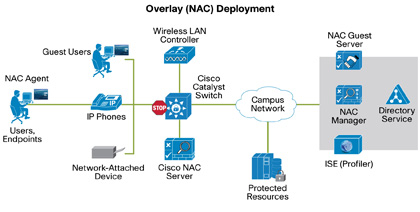
The Cisco Network Admission Control System, composed of the Cisco NAC Manager and Server, is a policy component of the Cisco TrustSec solution. You can deploy this system as an overlay solution for accounts requiring network authentication, role-based access control, and posture assessment.
Cisco NAC Appliance extends NAC to all network access methods, including access through LANs, remote-access gateways, and wireless access points. It also supports posture assessment for guest users. You can combine Cisco NAC with Cisco NAC Guest Server and Cisco NAC Profiler for additional features.

NAC Overlay Deployment

Saturday 4 May 2013

Windows Server 2012 editions


 Windows Server 2012 Datacenter is designed for
highly virtualized private cloud environments.
 Windows Server 2012 Standard is designed for
physical or minimally virtualized environments.
 Windows Server 2012 Essentials is ideal for small
businesses that have as many as 25 users and 50 devices.
 Windows Server 2012 Foundation provides a Windows
Server experience for as many as 15 users.


Step-by-Step Guide for Setting Up Windows Server 2012 Domain Controller


INSTALLING AD DS ROLE

“Before You Begin” screen provides you basic information such as configuring strong passwords, IP addresses and Windows updates.
On Installation Type page, select the first option “Role-based or Feature-based Installation“.
Scenario-based Installation option applied only to Remote Desktop services.
On the “Server Selection” Page, select a server from the server pool and click next.
To install AD DS, select Active Directory Domain Services in turn it will pop-up to add other AD DS related tools. Click on Add Features.
After clicking “Add Features” above, you will be able to click “Next >” as shown in the screen below.
On the “Select Features” Page, Group Policy Management featureautomatically installed during the promotion. Click next.
On the “Active Directory Domain Services” page, it gives basic information about AD DS. Click Next.
On the “Confirmation” Page, You need to confirm this to continue with this configuration. It will provide you an option to export the configuration settings and  also if you want the server to be restarted automatically as required.
After clicking “Install” the selected role binaries will be installed on the server.
After “Active Directory Domain Services” role binaries have been installed and now it is time to promote the server to a Domain Controller.
  

Technet Article:

PROMOTING WINDOWS 2012 SERVER TO DOMAIN CONTROLLER

To create a new AD forest called “ArabITPro.local”, select add a new forest.
Type the name ArabITPro.local
Specify the FFL, DFL, whether or not it should be a DNS Server and also the DSRM administrator password. As you can see, it has selected the GC option by default and you cannot deselect it. The reason for this is that is the very first DC of the AD forest and at least one needs to be a GC.
DNS delegation warning.
Checks the NetBIOS name already assigned.
Specify the location of the AD related folders and then click next.
Summary Of All Installation Options/Selections.
Click View script for single command  line powershell script for dcpromo.
Before the actual install of AD, all prerequisites are checked. If All prerequisite checks are passed successfully then click Install.
When you click Install, DNS and the GPMC are installed automatically.
After the promotion of the server to a DC finished server restart automatically.
Once the server is booted and you logon to it, click on  Server Manager | Tools ,  will notice that following have been installed :
•Active Directory Administrative Center
•Active Directory Domains and Trusts
•Active Directory Module for Windows PowerShell
•Active Directory Sites and Services
•Active Directory Users and Computers
•ADSI Edit
•DNS
•Group Policy Management